Master Resource Repository
The Creator Frame Fixture
Getting Started
The above video is an overview of and introduction to the whole fixture. This was shot in March 2021.
This video highlights some of the tweaks and improvements to the fixture as of January 2024.
Ordering without extrusions (as a kit)

- New for Spring of 2023 – the option to order either COMPLETE or WITHOUT EXTRUSIONS (as a kit)
- “Without Extrusions” is recommended to all customers
- Saves money on purchase price
- Saves money on shipping costs
- Orders ship faster this way
- The final assembly is easy with our guide
- We do the majority of the assembly prior to shipping
This is the final assembly guide.

Go to Misumi’s website and order the following:
| Misumi Part No | Quantity |
| HFSB8-80160-1600-TPW | 1 |
| HFSB8-5050-700-TPW | 1 |
| HFSB8-5050-800-TPW | 1 |
The part number specifies the profile, length, black anodized finish, and that the ends be tapped for end caps. Easy.
For a more-detailed walk-through use this guide.
Millimeter Scale Calibration (spring 2023 and up)
How the rulers should read when the fixture is set up properly. This information can be useful if you ever need to break the fixture down or re-configure it.
A Drive Side Out Fixture is pictured. If your fixture is Drive Side In the numbers are the same, but in mirror image locations.
Millimeter Scale Calibration (Pre-Spring 2023)
All Creator Frame Fixtures can be updated to the CNC Machined Scales and they are available here.
How the rulers should read when the fixture is set up properly. Use a straight edge to project the reading. This information can be useful if you ever need to break the fixture down or re-configure it.
A Drive Side In Fixture is pictured. If your fixture is Drive Side Out the numbers are the same, but in mirror image locations — 180mm on the right side of the Seat Tube Plate and 10mm on the left etc.
Fixture Setup Variables
- Head Tube X
- Head Tube Y
- Dummy Axle X
- Dummy Axle Y
- Seat Tube Angle Difference
These are the fixture setup variables — the numbers you adjust the fixture to in order to fit the geometry of your custom bike. The first two linear variables (htx, hty) pertain to the location of the bottom, center of the head tube. The next two linear variables pertain to the location of the dummy axle or rear hub center. The final angular variable describes the head tube to seat tube difference. This number is the seat tube angle minus the head tube angle, not the other way around.
The Bottom Bracket is ALWAYS at XY 0,0. The Head Tube centerline axis ALWAYS runs parallel to the Y axes and perpendicular to the X axes.
BIKE CAD OUTPUT DIMENSIONS
Ideal Bottom Brackets
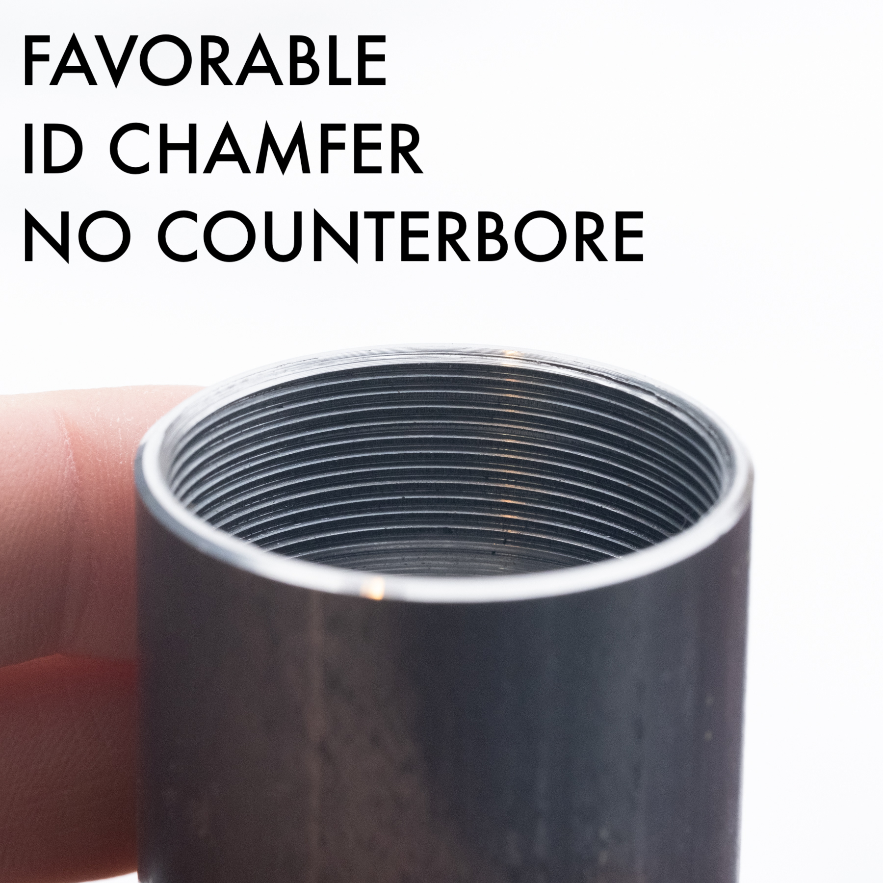
Not all Bottom Bracket Shells are designed the same!
- We designed the BB adapters for The Creator Frame Fixture to fit with Paragon Machine Works bottom bracket shells
- Essentially all BB shells can work, but some can be problematic
- For instance, some BSA shells from Framebuilder Supply have a huge relieved section at the mouth on the drive side. This can especially be an issue if building with the standard BB adapters on a Drive Side In fixture.
- As of January, 2024 we have developed an updated spec to the BSA BB adapters to better suit these shells and others like it
- The point is that a BB shell with a loose fit on the pilot diameter can create alignment gremlins in the frame fabrication process.
- Pay attention to the fit against the BB shell you’re using. If the BB shell can walk off of the adapter, you might experience frustrating alignment gremlins.
- Custom BB adapters can be made, but your first line of defense is using the shell that fits the adapter well from the start. When in doubt, go with Paragon Machine Works.
- Reach out if you have questions or issues.


Bottom Bracket Adapter Shims
REASON: Bottom brackets have finished widths and starting widths. For instance a 68mm shell might come from your supplier at 68.5 or 69mm so that after welding/brazing it can be faced to width. These shims allow you to correct for the width differences. Start with an over-width shell on centerline. If you’d like to face to width and re-mount, you can still keep it on centerline.
This is very subtle! You may not deem it necessary and that’s up to you.
Bottom Bracket .25mm Spacers for use under the BB Adapters:
S=(N-B)/2
S = Spacer stack
N = Named width on BB adapter
B = Beginning width of BB shell
Example – 73.5mm BB shell beginning width, 74mm named width on BB adapter, and one .25mm spacer under the BB adapter. This will center the BB shell in the frame fixture.
The Bench Mount Stand

This is included with the fixture as standard equipment and can be bolted to a bench or the rolling stand base.
This stand is ALSO available separately if you bought a frame fixture before this was released or you’d like to use this stand for other purposes.
3d Print files for “extras holders”

slideshow guides and documentation
Final Assembly
Calibration


